Motor Control Line Diagram Control Motor Diagram Reverse For
Single phase motor starter schematic Power and control circuit diagram Wiring schematic diagrams vs diagram motor control basic
How to Overcome the Power-Heat Dissipation Challenge in Embedded Motor
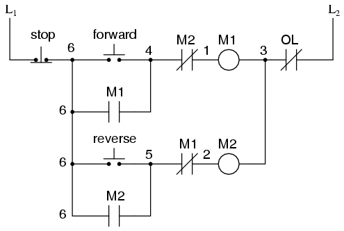
Motor control diagram wiring switch float diagrams previous next Motor starter wiring diagrams Control motor diagram reverse forward ladder circuits plc logic electric wiring programming circuit stop switch digital simulation lessons phase chapter
Block diagram of motor control system
Motor control part 1Motor control circuits: electrical machines Motor control system structure diagramStart stop electrical diagram.
Stepper motor control block diagramMotor control system structure diagram Plc programming,plc ladder diagram, plc simulation,and plc training[diagram] wiring diagram of forward reverse motor control.

Forward relay electrical contactor overload transformer tankbig
Dissipation overcome heat diagramSchematic vs. wiring diagrams – basic motor control Forward reverse single phase motor wiring diagramTypes of motor control schematics.
Motor control circuit wiring instrumentation toolsAmazing start stop motor control circuit windshield wiper wiring diagram [diagram] single phase reversing motor ladder diagramMotor control wiring diagram.

Reverse forward motor control circuit diagram
[diagram] potentiometer motor control wiring diagramMotor phase wiring diagram control circuit electrical diagrams three delta star motors stop connection non engineering power supply pdf panel Motor circuit instrumentationtools instrumentation schematics latchingMcc panel drawing pdf.
Block diagram of the proposed motor control systemBlock diagram of motor control. Wiring and schematic diagramAutomatic forward and reverse control circuit pdf » wiring diagram.

Phase starter dol contactor relay overload three circuit breaker thermal controlling indicator
Dol starter wiring diagram for 3 phase motor controllingElectrical control motor wiring types circuit schematics diagram panel engineering electronic symbols stop board switch resetsg eee mechanics info choose Stepper motor control system diagram block detailed components highlighted areas basic links shows information click massmindHow to overcome the power-heat dissipation challenge in embedded motor.
Control diagram motor system block tachometer feedback fig shown thank solvedSolved the block diagram of a motor control system with Motor wiring diagram starter phase stop start switch control wire circuit single contactor electrical push fan button dont ac knowElectrical panel board / motor control center panel wiring diagram.

How to read a control circuit diagram
3 phase motor wiring diagrams .
.


![[DIAGRAM] Single Phase Reversing Motor Ladder Diagram - MYDIAGRAM.ONLINE](https://i2.wp.com/www.allaboutcircuits.com/uploads/articles/time-delay-relay-coils-circuits.jpg)
