Nand-naand One Bit Comparator Circuit Diagram Nand Comparato
Nand circuit diagram Nand-based four-input clocked comparator proposed by ojima et al. [21 Nand diode
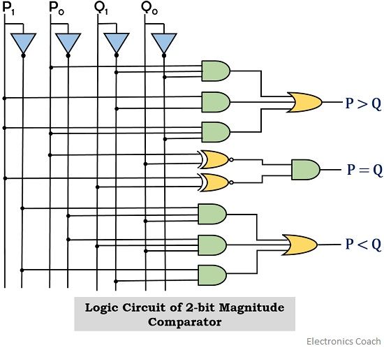
1 Bit Magnitude Comparator Circuit Diagram
[diagram] logic diagram of 2 bit magnitudeparator Logic circuit for 1-bit magnitude comparator Explain 2-bit comparator circuit
Comparator logic diagram
Block diagram logic circuit 1-bit comparator.Binary comparators 4 bit magnitude comparator circuit diagramCmos nand gate circuit diagram.
Comparator bit magnitude digital electronics binary equality comparators four fig learnabout10 input nand gate png Magnitude comparator and digital comparator : types & their applications☑ diode resistor logic nand gate.

3 input nand gate schematic
Nand gate diagramIntroduction to logic gates How can we design a 2-bit comparator circuit with four 2-input nand1-bit comparator.
Design 2 bit comparator using logic gatesBit circuit two comparator boolean expression truth table binary need thanks watson please behavior latech edu Magnitude comparator bit diagram circuit digitalDesign 4-bit comparator circuit using gates.

Settlers motto auction 3 input nand gate truth table see through
Design 4-bit comparator circuit using gates5.1 comparator using nand Digital comparator and magnitude comparator tutorialComparator diagram circuit.
Nand comparator multisimSolved implement a 3-bit comparator circuit using nand 2 bit comparator circuit diagram1 bit magnitude comparator circuit diagram.
Digital comparator circuit diagram
Cmos or gate circuit diagramVerilog code for comparator using nand Solved assignment description: design a one-bit nor/nandComparator bit magnitude circuit logic digital electronics.
Logic nand gate working principle & circuit diagram .


